IS-F08 Thermal Control Board

IS-F08 Thermal Control Board

Product Code: Fan Sensor Board
Product available in stock : 10
  • £15.00


rightbanner
2 year warranty
on all new Power Supply Units
  • Free UK shipping:
    On ALL products
  • Fast shipping:
    Usually within 1 day
  • Worldwide shipping:
    Order from anywhere
  • 24/7 support:
    Contact us by E-mail
  • 100% satisfaction:
    30-day return policy
  • 2-year warranty:
    On ALL PSUs
IS-F08 Thermal Control Board — Description

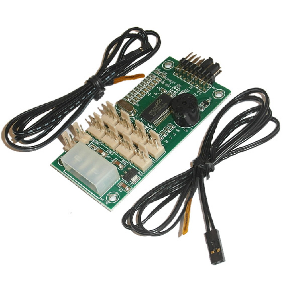
The IS-F08 is a compact thermal control board designed to monitor and protect your equipment against overheating and fan failure. Ideal for 19" rackmount enclosures, it supports up to 8 cooling fans and 2 independent temperature sensors, with audible and visual alerts when thresholds are exceeded.

Fan support

Up to 8 fans (3-pin)

Temperature sensors

2 supplied (72 cm wire)

Temperature thresholds

50°C / 60°C / 70°C

Power connector

Standard Molex 4-pin

Board dimensions

40 × 80 mm

Mounting hole span

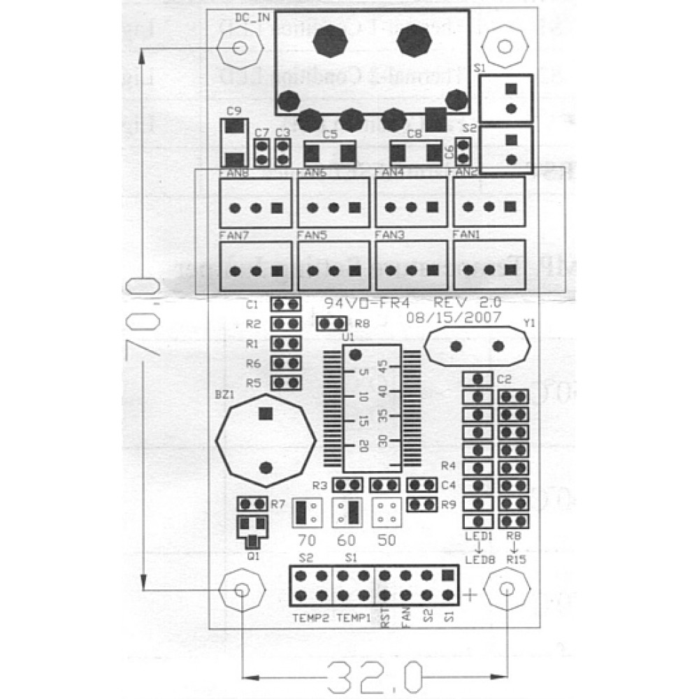
70 × 32 mm (4 screws)

Weight

55 g

Alarm thresholds

50°C / 60°C / 70°C

  • Monitors up to 8 cooling fans simultaneously with per-fan failure detection
  • 2 independent temperature sensors with flat heads — easily taped onto the components being monitored
  • 3 selectable alarm thresholds via jumper: 50°C, 60°C, or 70°C, configurable individually per sensor
  • Audible buzzer and flashing LED alerts for both fan failure and overheating events
  • Compatible with optional front-panel reset switch and status LEDs
  • Supplied with plastic insulating sheet to prevent short circuit against the chassis
  • Especially designed for most 19" rackmount enclosures; adaptable to other enclosures with proper insulation
IS-F08 Thermal Control Board — User Manual

Installation

  1. 1.

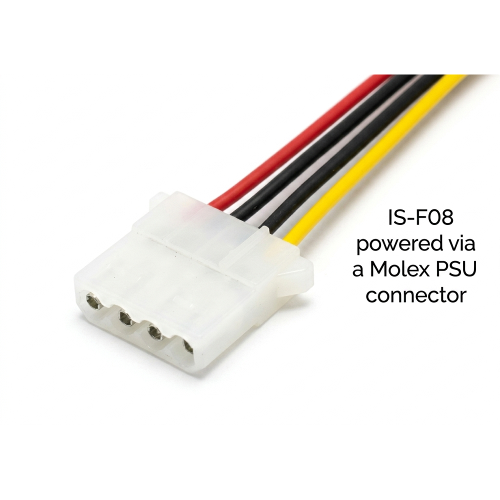
    Connect the IS-F08 to a standard Molex 4-pin power connector from the power supply.

  2. 2.

    Mount the board using the 4 supplied screws. If installed outside a 19" rack (e.g. a standard PC chassis), insert the supplied plastic sheet between the board and the chassis to avoid short circuit.

  3. 3.

    Connect your 3-pin clock-type fans to the fan headers. The detection IC will automatically identify the number and position of connected fans at power-on.

  4. 4.

    Attach the flat-head temperature sensors (S1, S2) to the components you wish to monitor using tape. Each sensor wire is 72 cm long.

  5. 5.

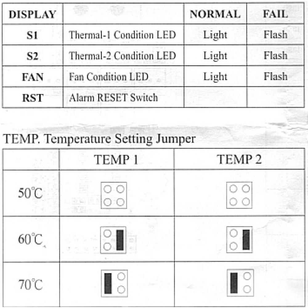
    Set the temperature alarm threshold for each sensor using the jumpers (see table below).

Jumper temperature settings

Threshold Recommended use Sensor
50°C Sensitive components — early warning S1 and/or S2 (independent)
60°C Standard equipment — general use S1 and/or S2 (independent)
70°C High-performance components — max tolerance S1 and/or S2 (independent)

S1 and S2 can be set to different thresholds. Incorrect jumper setup may trigger false alarms.

Alerts & normal operation

  • Fan LED on (steady): all connected fans are functioning normally.
  • Fan LED flashing + buzzer: one or more fans have failed. Identify and replace the faulty fan, keeping it in the same connector position.
  • S1/S2 LED flashing + buzzer: the corresponding sensor has detected overheating. Identify the hot component and address cooling immediately.
  • RESET button: silences the buzzer temporarily. If the LED continues to flash after reset, the fault must be resolved before normal operation resumes.

Troubleshooting

  1. 1.

    Fan failure alarm: Press RESET to stop the buzzer. If the LED keeps flashing, replace the faulty fan and reinstall it in the exact same position — changing positions will trigger a new alarm.

  2. 2.

    Temperature alarm: Press RESET to stop the buzzer. If the S1 or S2 LED keeps flashing, improve cooling for that component or review the jumper threshold setting.

  3. 3.

    System not functioning: Check for a power shortage, a malfunctioning fan, or a faulty temperature sensor.

Important: Always power off the system before moving the control board or unplugging the 4-pin Molex connector. Hot-unplugging can damage the IC or the circuit board. Fans must be 3-pin clock type — other fan types are not supported. Never relocate a fan while the board is powered on.

Specification
Model Number IS-F08
Colour Green
Product size & weight 40 x 80mm, 55g
More Info
Package size & weight 20 x 15 x 2cm, 100g
Product Condition Brand new
Return Return accepted within 30 days if unwanted.
Made in China
Shipped from United Kingdom
Remarks Your rackmount or PC chassis requires a mounting hole span of 70 x 32mm. 4x M3 screws are supplied.

Write a review

Note: HTML is not translated!
    Bad           Good
Captcha