PSU connectors
PSU Connectors Explained
Every power connector on a modern PSU — pin counts, voltages, wire colours, pinout diagrams and what each one powers.
Every component needs a specific power connector, and PSU connectors are deliberately keyed so plugging into the wrong socket is virtually impossible. The exception is a small handful of look-alikes (EPS vs PCIe being the classic one) — exactly why this guide exists.
This page covers every connector from a PSU — essentials, peripheral/legacy, vintage AT-era, the newest GPU standard, and proprietary NAS connectors. See our How to Choose a PSU guide for buying advice, or our PSU Measurements guide for dimensions.
- Wire Colour Code — what every colour means
- Motherboard & CPU Power — the essentials
- Graphics Card Power — including the new 12V-2x6
- Storage & Drive Power
- Peripheral & Legacy Connectors
- AT / Vintage Connectors
- Proprietary & Custom Connectors
- Quick Reference Table
- Not Listed Here?
- Quick-Reference Checklist
Wire Colour Code: What Every Colour Means
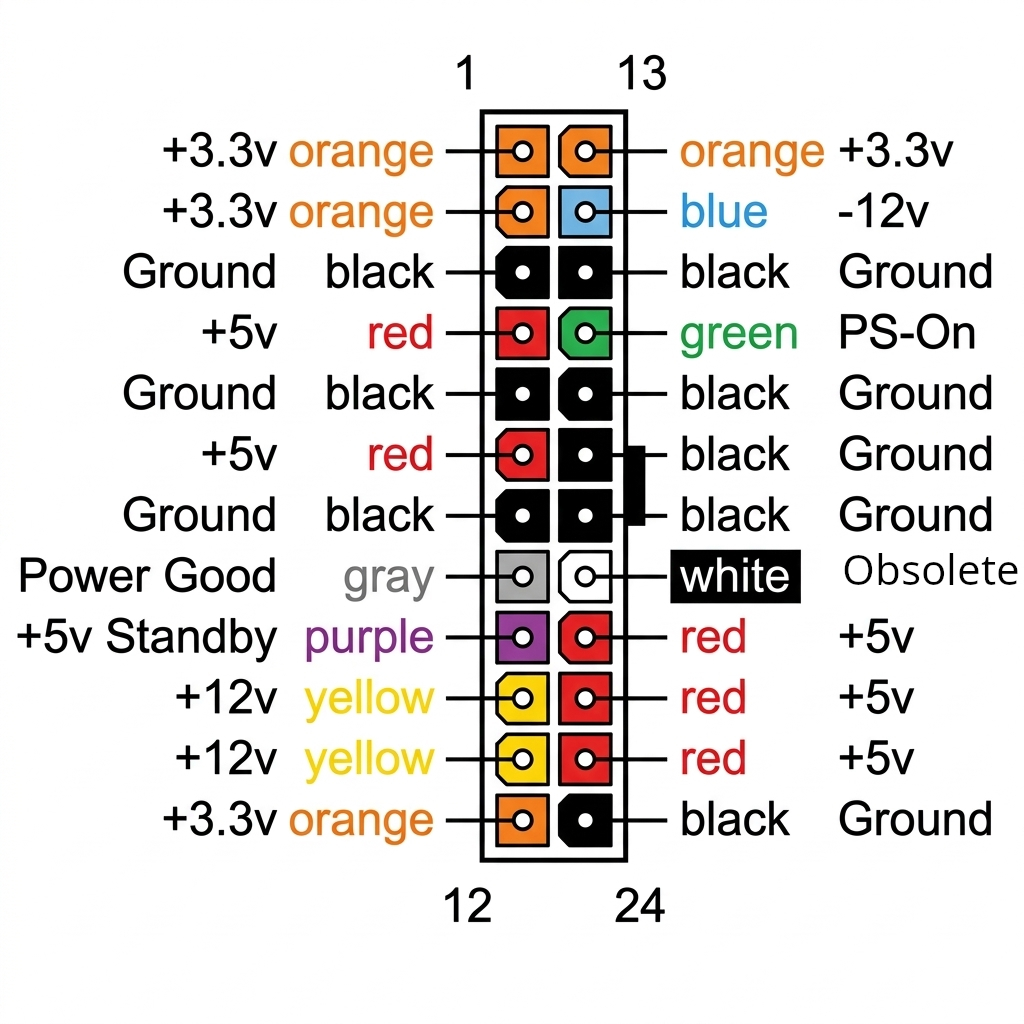
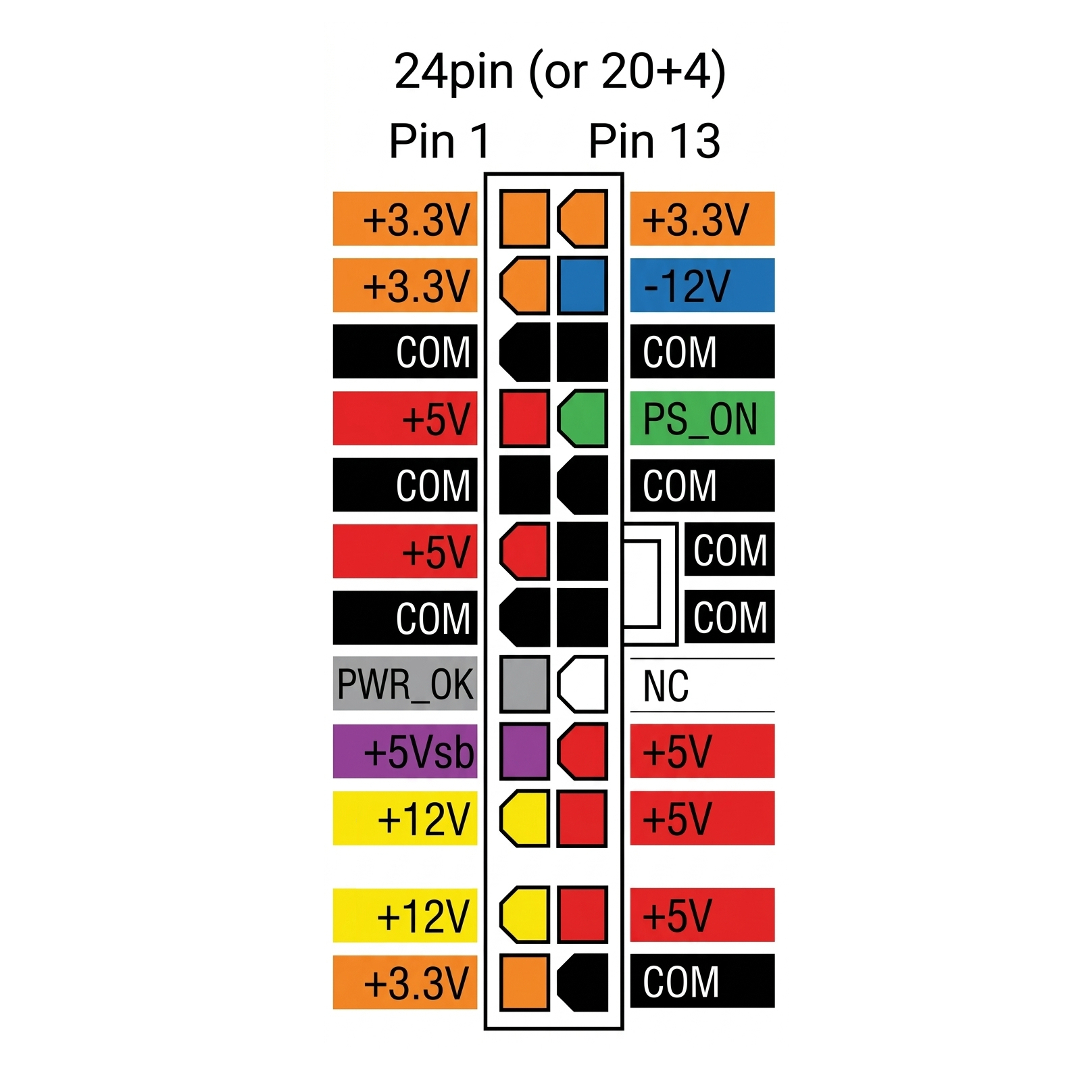
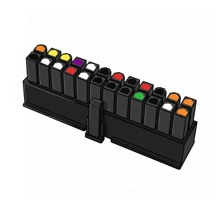
Every connector on this page follows the same standard wire colour code — shown on the 24-pin ATX pinout below, and carrying through to EPS, PCIe, SATA and Molex too.
| Colour | Voltage / Signal | What it's for |
|---|---|---|
| Orange | +3.3V | Low-voltage rail — chipset, some SSDs and USB circuitry |
| Red | +5V | Legacy peripherals, drive logic boards, USB devices |
| Yellow | +12V | The primary modern rail — CPU, GPU, motherboard, drive motors |
| Black | Ground (0V) | Return path for every rail — always paired with a coloured wire |
| Blue | -12V | Legacy negative rail, rarely used by anything modern |
| Purple | +5V Standby | Stays live even when the PC is "off" — powers USB charging and wake-on-LAN |
| Green | PS_ON (signal) | Not a voltage — the motherboard pulls this low to switch the PSU on |
| Grey | Power Good (signal) | Not a voltage — the PSU pulls this high once its output is stable |
| White | -5V | Obsolete — legacy ISA bus slots, some old sound cards, and DRAM refresh circuitry; dropped from the ATX spec and absent on modern PSUs, but still present on legacy AT PSUs |
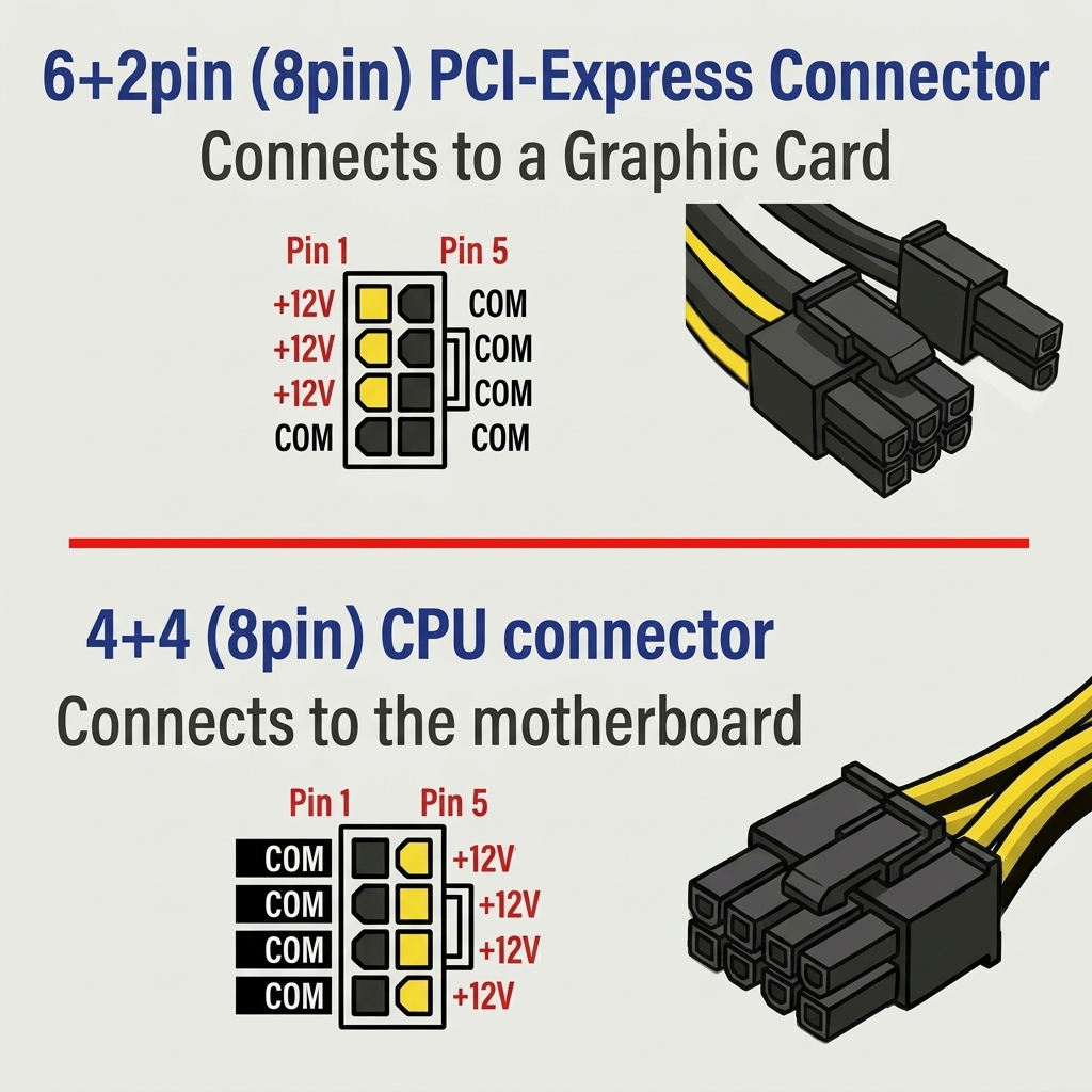
Motherboard & CPU Power
Every ATX PC needs both a main connector and a CPU connector — neither has a substitute.
- Pins
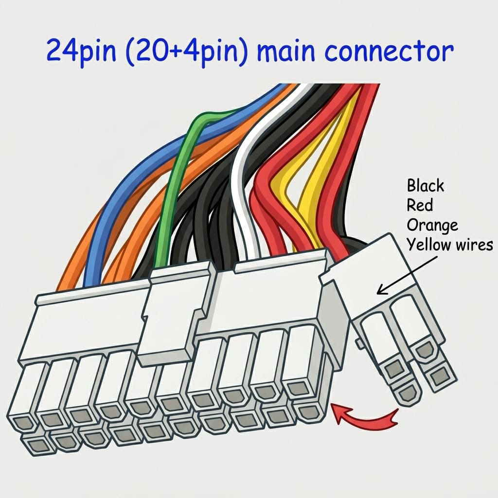
- 24 (splits to 20+4)
- Voltages
- +3.3V, +5V, +12V, -12V
- Wire colours
- Orange, red, yellow, black
- Introduced
- ATX (1995), 24-pin since 2003
The primary connector into the motherboard, supplying chipset, RAM, expansion slots and standby power. The 4-pin block detaches for compatibility with older 20-pin boards. Every ATX PSU includes this.
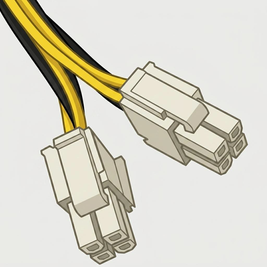
- Pins
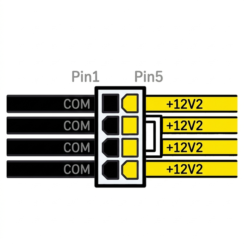
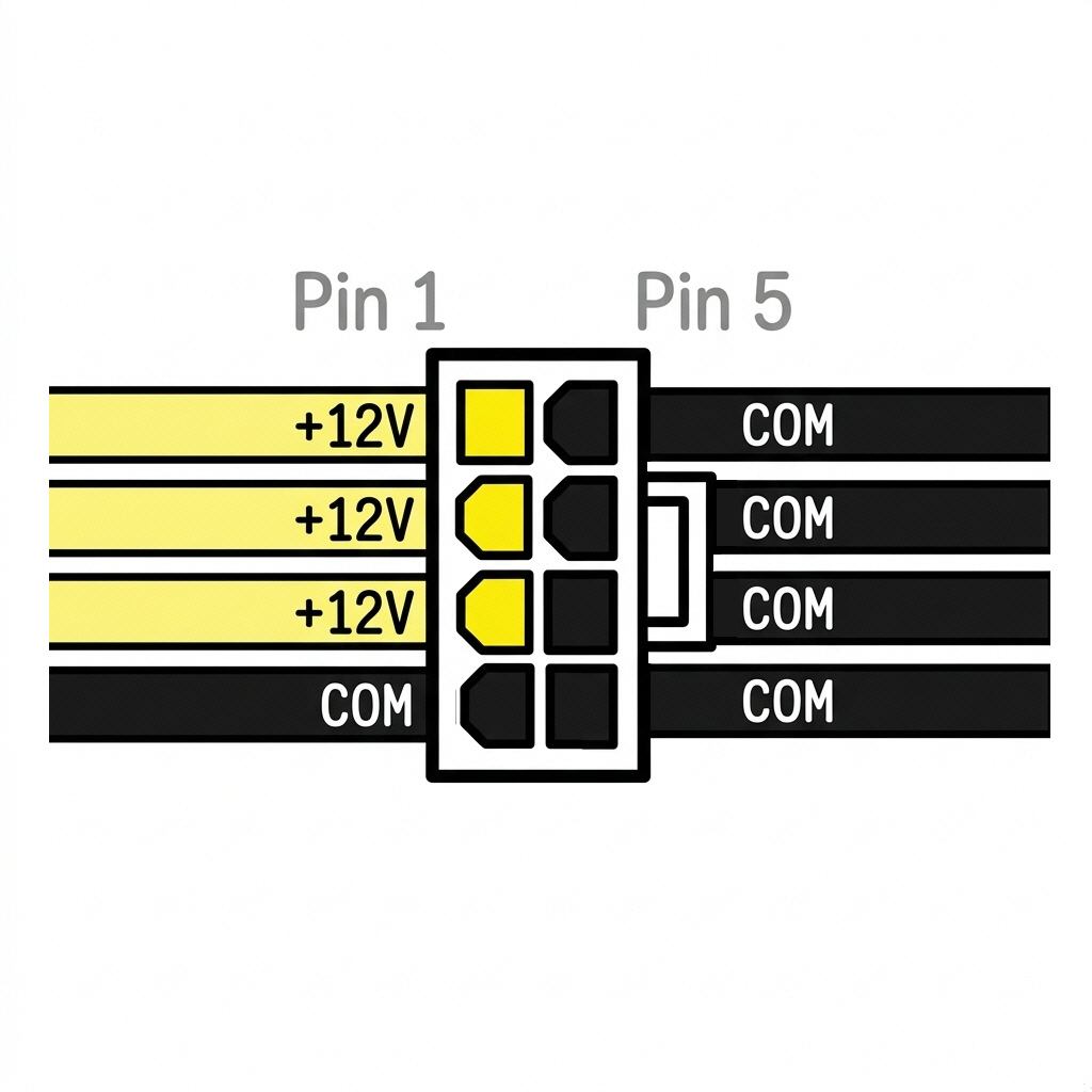
- 8 (splits to 4+4)
- Voltage
- +12V only
- Wire colours
- Yellow (+12V), black (GND)
- Also called
- EPS12V, CPU 8-pin
A dedicated +12V feed to the CPU socket, kept separate from the ATX main connector for a clean, high-current supply. Demanding CPUs and dual-socket boards sometimes need two full 8-pin connectors.
- Pins
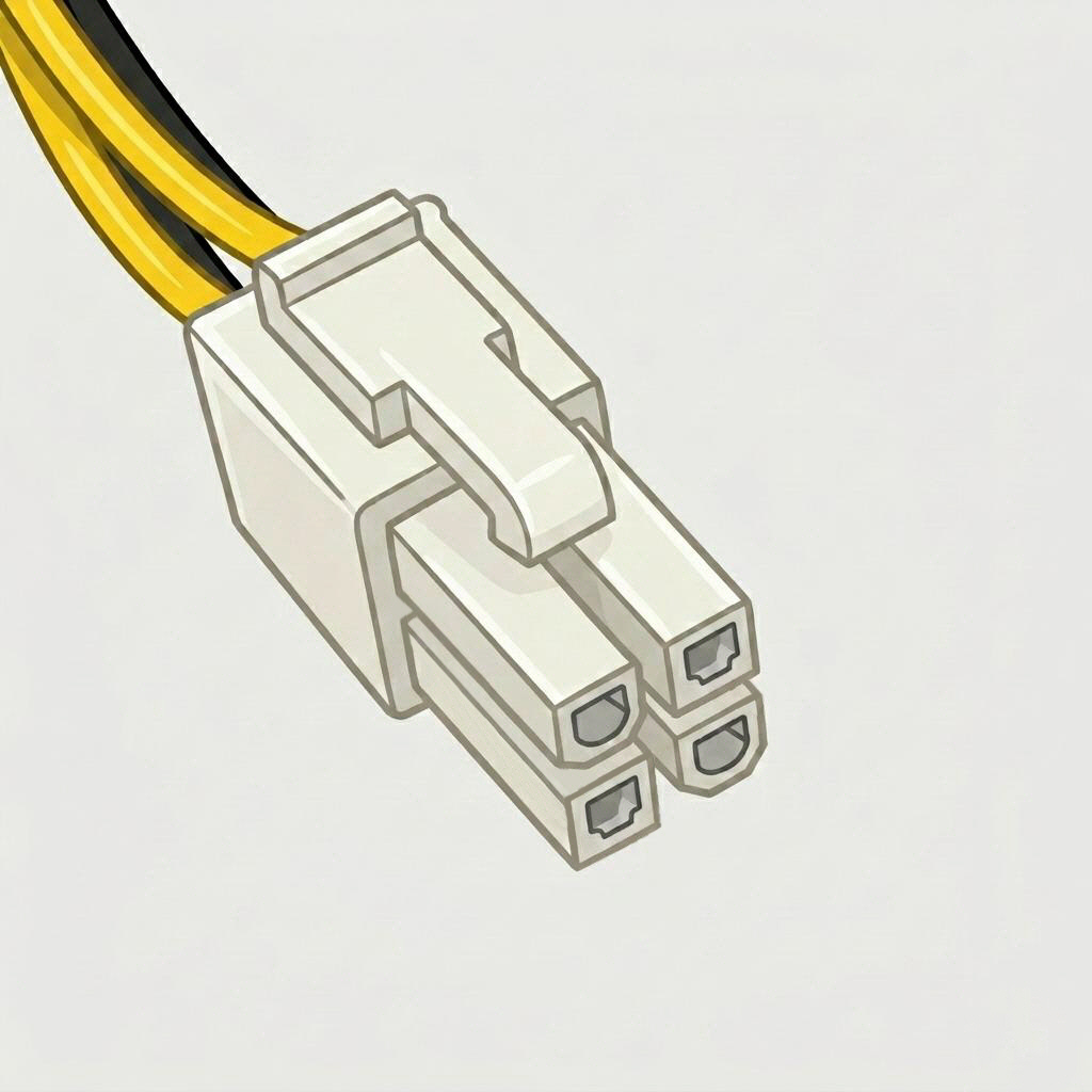
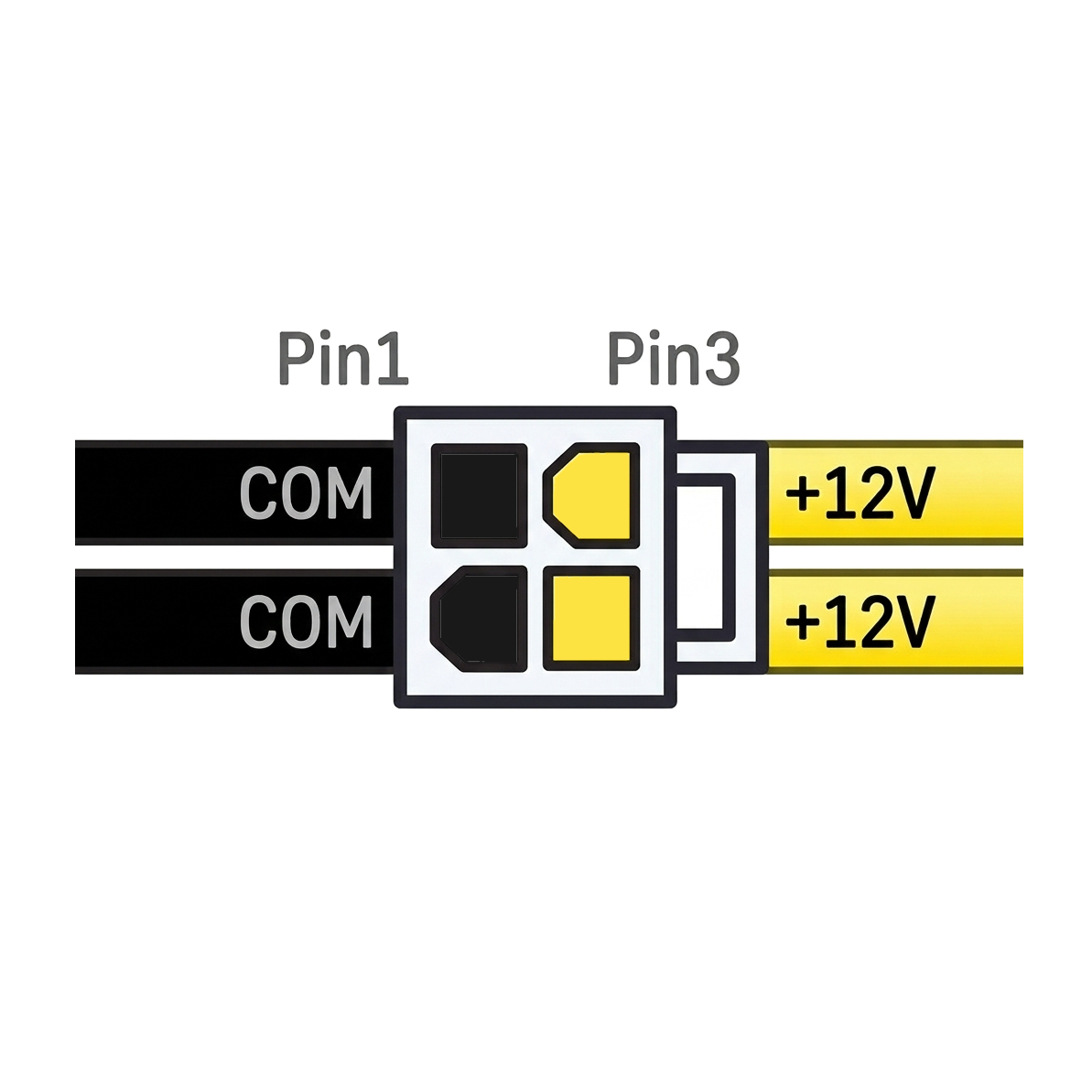
- 4
- Voltage
- +12V only
- Wire colours
- Yellow (+12V), black (GND)
- Also called
- ATX12V, P4 connector
The single 4-pin half of the EPS connector, used alone on older or budget boards from before the 8-pin standard became universal. Still turns up on some entry-level boards today.
Graphics Card Power
Only needed if your GPU draws more than the 75W the PCIe slot itself supplies — true of almost every dedicated GPU beyond entry-level.
- Pins
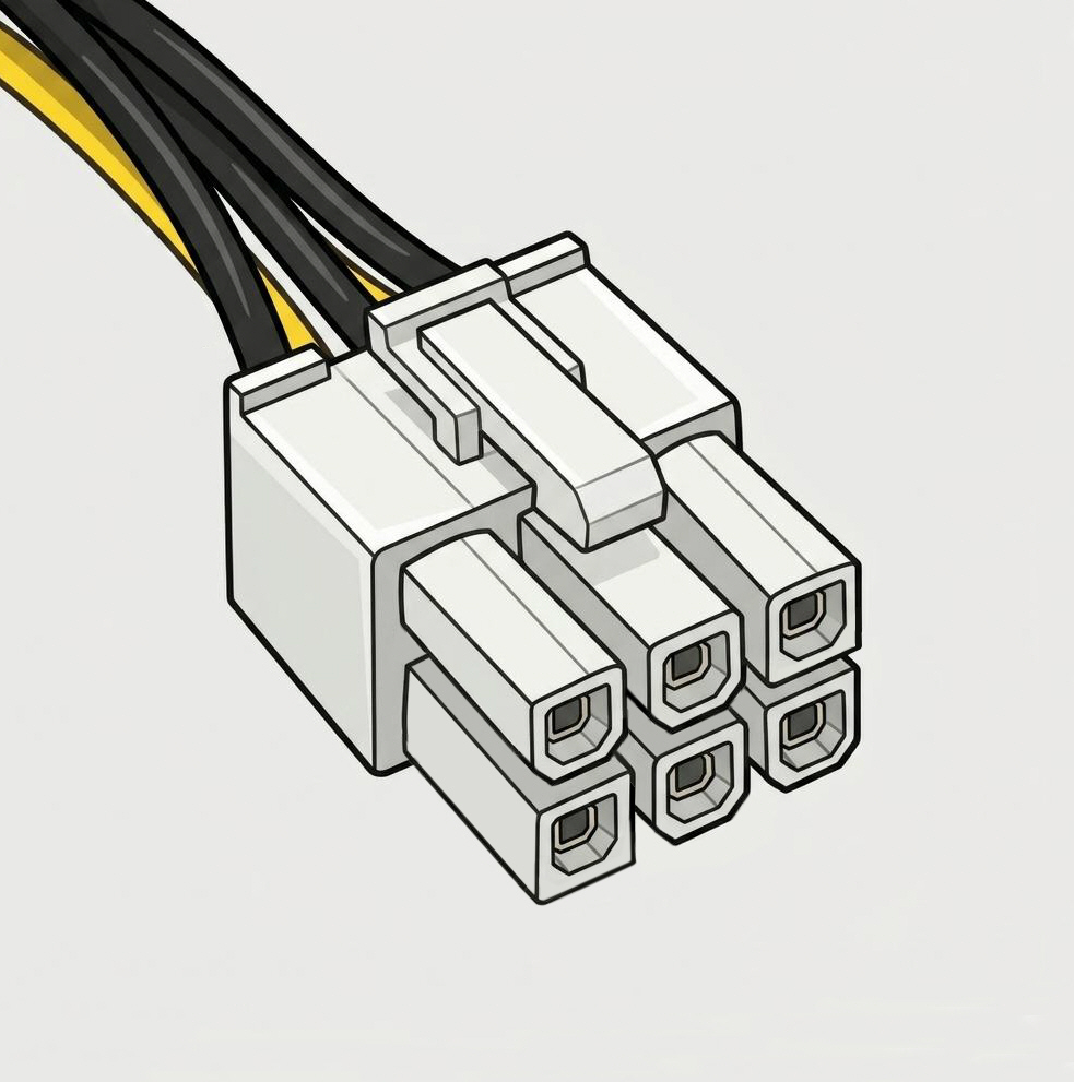
- 6
- Voltage
- +12V only
- Wire colours
- Yellow (+12V), black (GND)
- Max power
- ~75W per connector
Supplies entry and mid-range GPUs that need more than the PCIe slot alone provides. Increasingly rare on new PSUs as GPUs get power-hungrier, but still included on many mid-range units.
- Pins
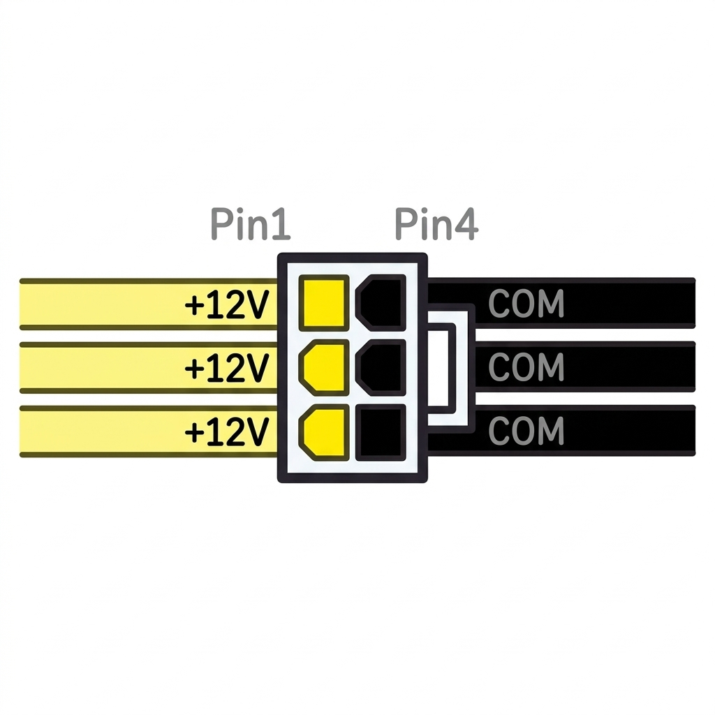
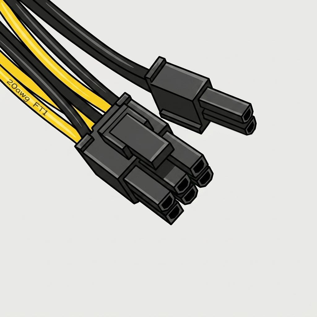
- 8 (6+2 split)
- Voltage
- +12V only
- Wire colours
- Yellow (+12V), black (GND)
- Max power
- ~150W per connector
The standard connector for most mid-to-high-end GPUs; the 2-pin section clips off to double as a 6-pin when needed. Higher-end cards often need two or three — check your GPU's requirement.
- Pins
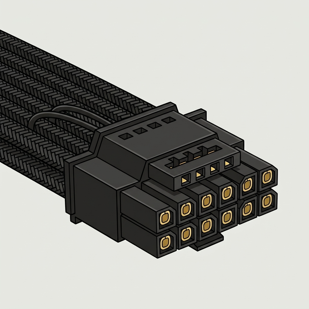
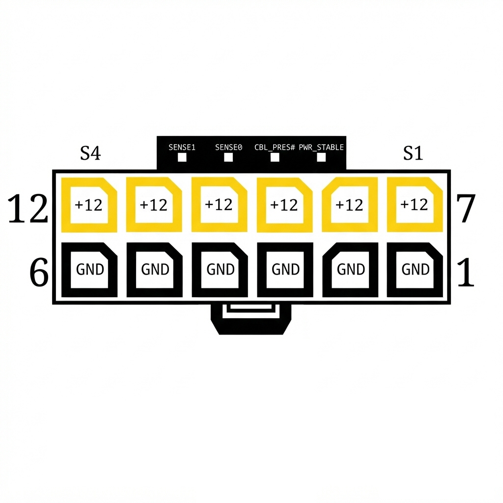
- 16 (12+4)
- Voltage
- +12V only
- Max power
- Up to 600W (single cable)
- Introduced
- ATX 3.0 (2022), refined ATX 3.1 (2023)
A single high-density connector replacing up to three 8-pin cables, introduced for RTX 40-series GPUs. The original 12VHPWR gained a reputation for melting when not fully seated; the revised 12V-2x6 shortens the sense pins so the card won't draw power unless clicked home. The two are cable-compatible.
Storage & Drive Power
Powers hard drives, SSDs and optical drives. Every PSU includes at least a few on a shared cable chain.
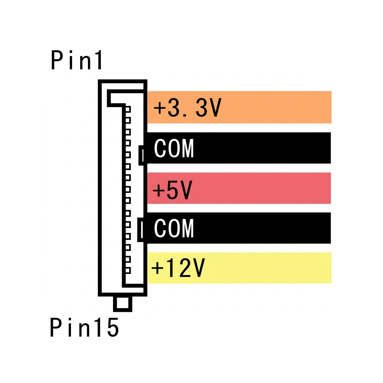
- Pins
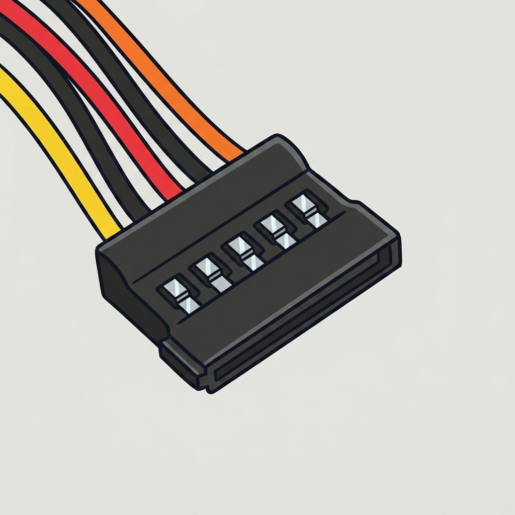
- 15 (wafer)
- Voltages
- +3.3V, +5V, +12V
- Wire colours
- Orange, red, yellow, black
- Also called
- SATA power connector
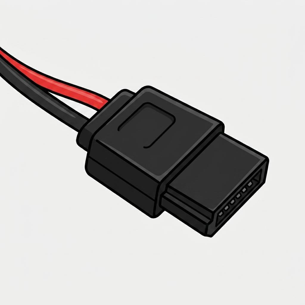
Powers SATA hard drives, SSDs and optical drives. The three voltages are each supplied by three ganged pins, with PSUs typically providing several on one daisy-chained cable. A right-angled version is also available.
- Pins
- 6
- Voltages
- +5V, +12V (compact)
- Use case
- Tight enclosures
A compact SATA power connector for tight spaces — slimline desktops, NAS enclosures and some Mini-ITX systems.
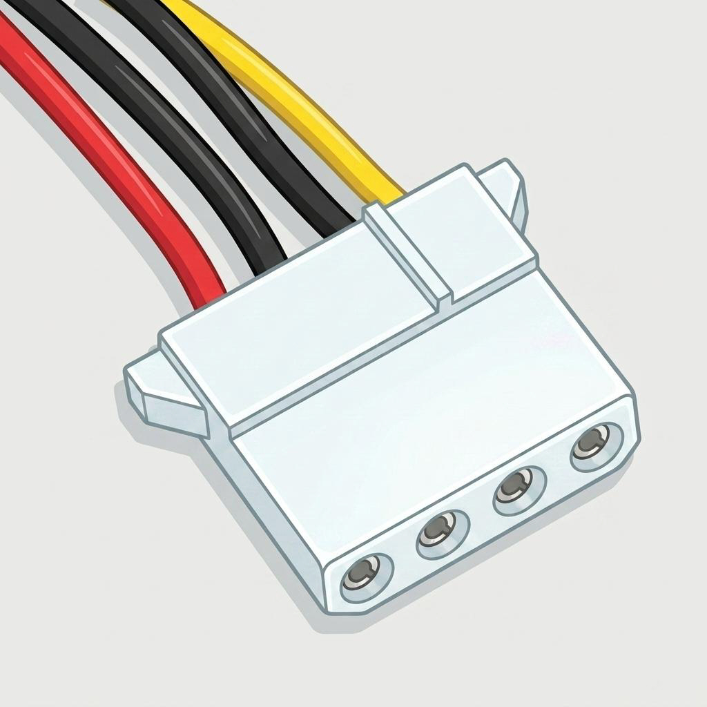
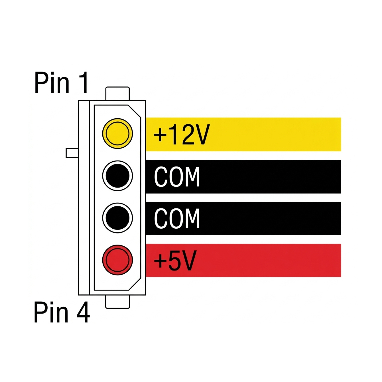
- Pins
- 4
- Voltages
- +5V, +12V
- Wire colours
- Red (+5V), yellow (+12V), black ×2 (GND)
- Also called
- Peripheral connector, IDE Molex
The older peripheral standard, predating SATA power. Still included on most PSUs for case fans, fan controllers, RGB hubs and adaptor cables.
Peripheral & Legacy Connectors
Unlikely on a modern build, but these still turn up on certain PSUs, older systems and adaptor cables.
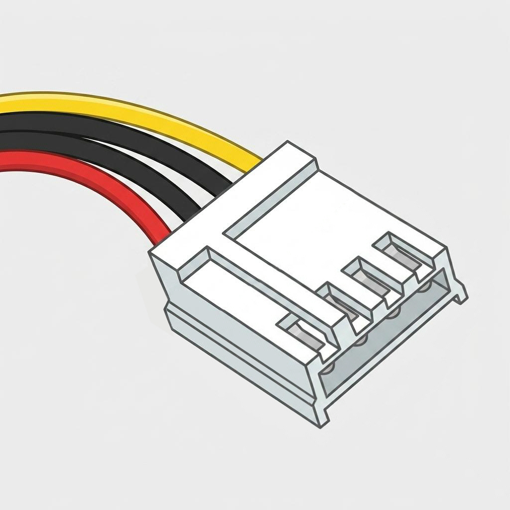
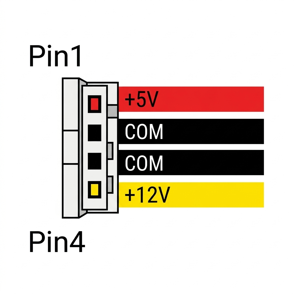
- Pins
- 4 (miniature)
- Voltages
- +5V, +12V
- Wire colours
- Red (+5V), yellow (+12V), black ×2 (GND)
- Also called
- Mini-Molex, Berg connector
Historically powered floppy disk drives — same voltage scheme as Molex, just physically smaller. Occasionally still required for fan controllers and adaptor cables.
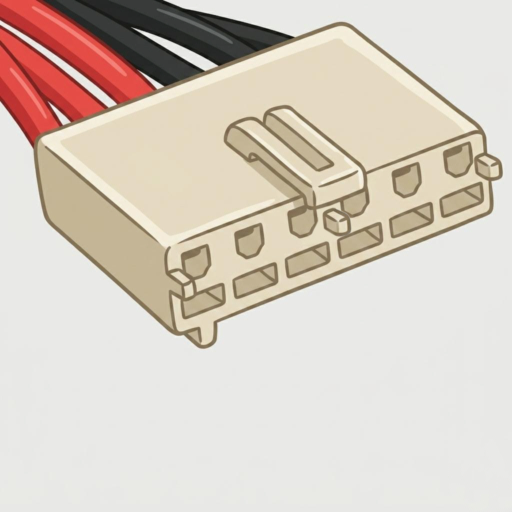
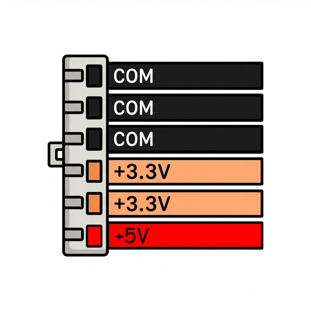
- Pins
- 6
- Voltages
- +3.3V, +5V
- Era
- Early-2000s ATX
Supplied extra 3.3V/5V current on some early-2000s ATX boards, before EPS became standard. Not to be confused with the visually similar PCIe 6-pin — pinout and purpose differ.
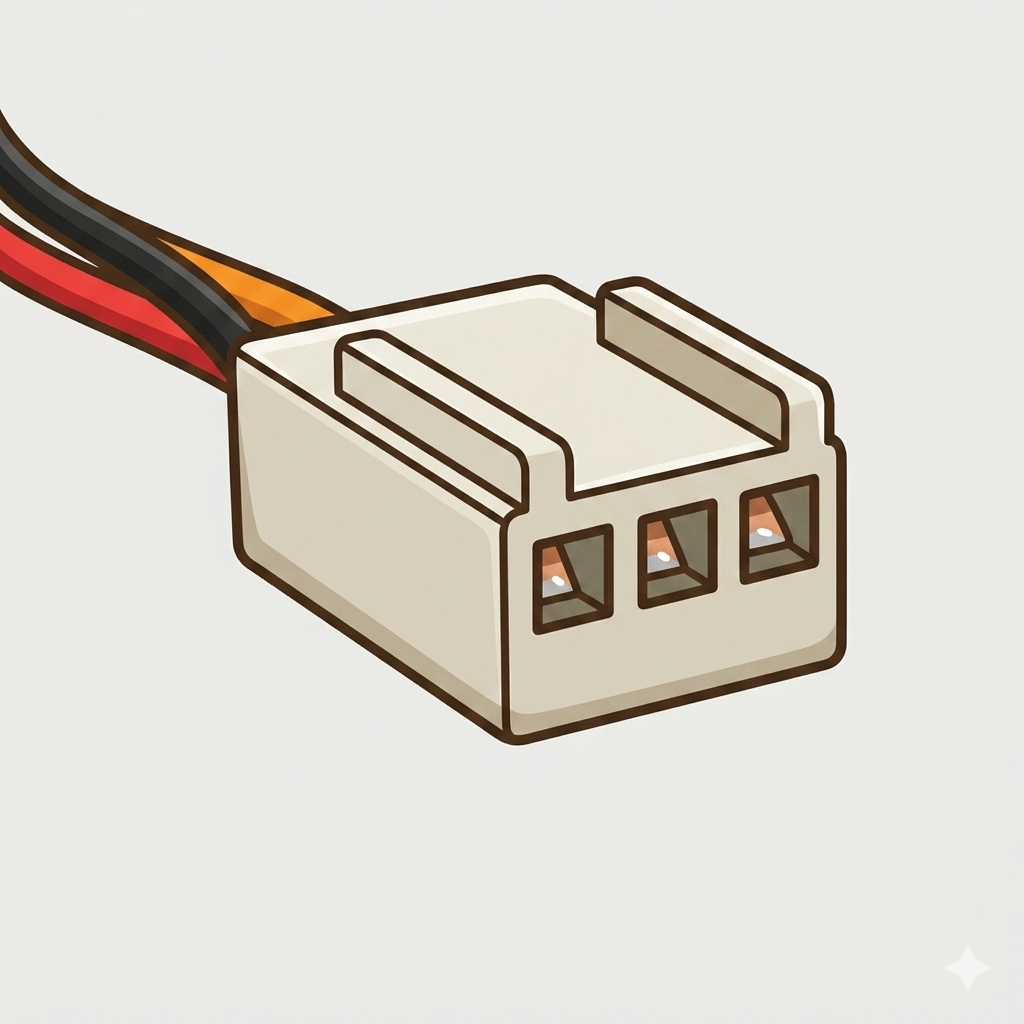
- Pins
- 3
- Voltage
- +12V
- Status
- Obsolete
Found on older supplies to power the unit's own cooling fan externally. Now obsolete — modern PSUs wire and control their fan internally.
AT / Vintage Connectors
Found exclusively on AT-standard supplies, which predate ATX. Relevant only for retro builds and legacy equipment.
- Pins
- 6 + 6 (two connectors)
- Used on
- AT PSUs only
- Replaced by
- Single 20/24-pin ATX
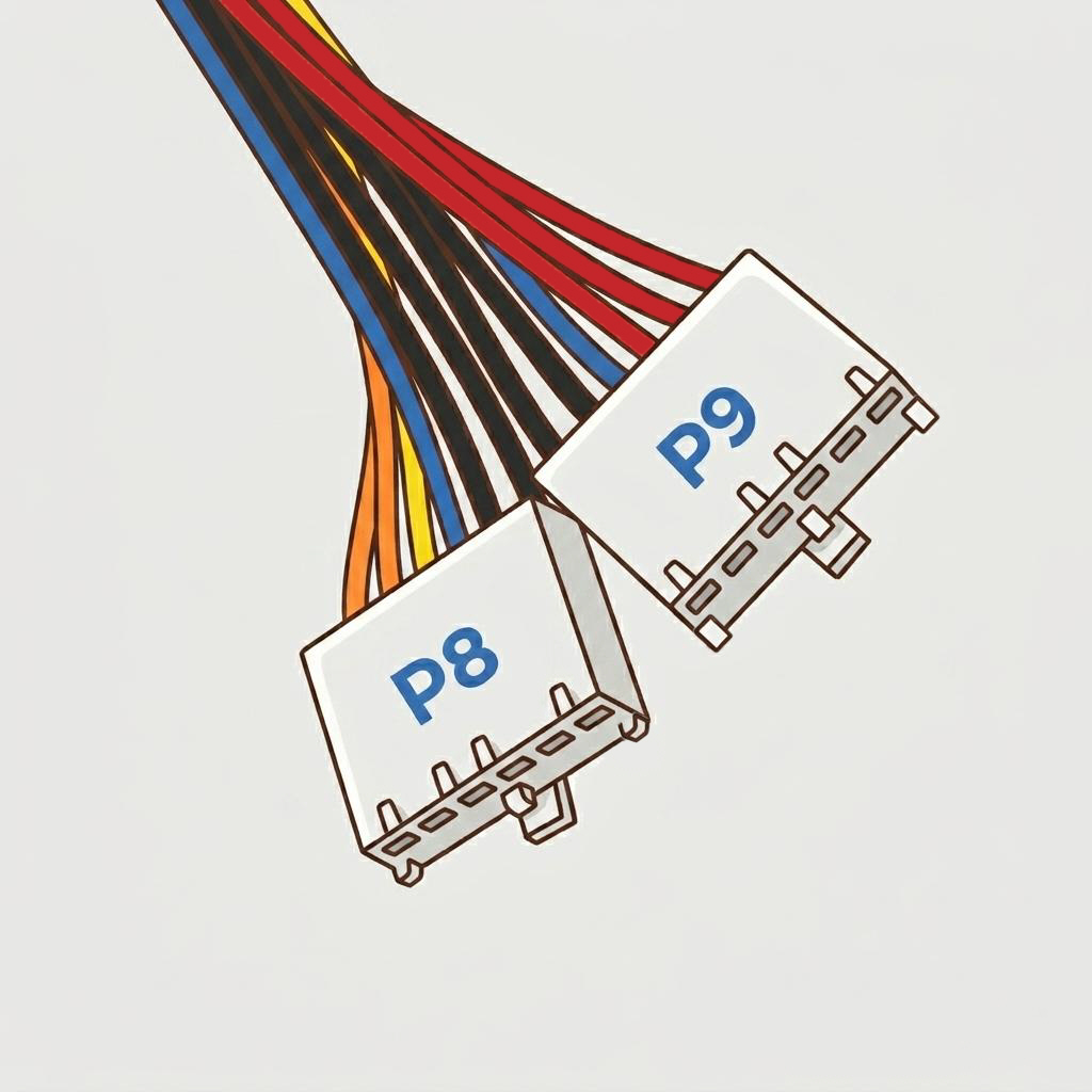
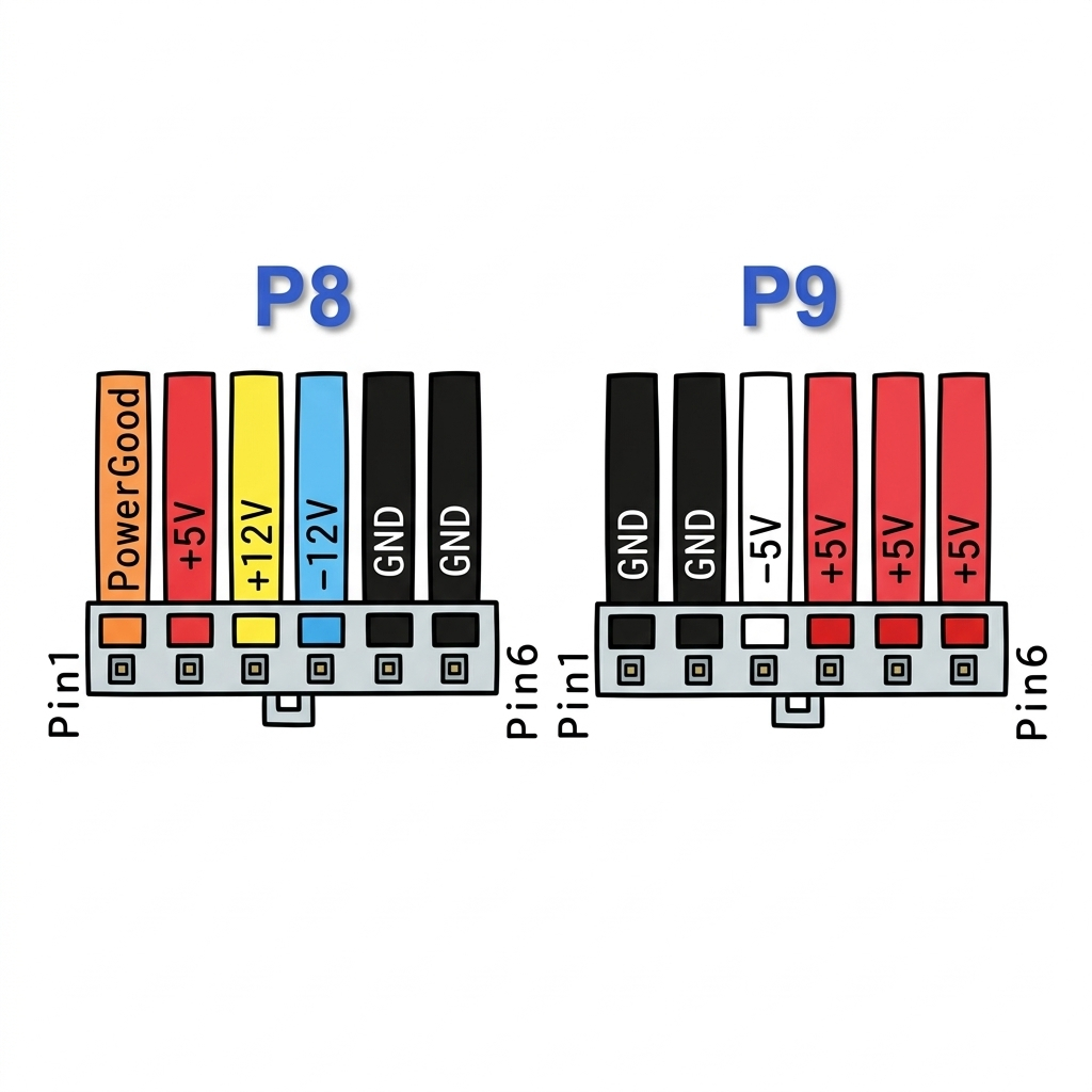
Two separate 6-pin connectors doing the job the single ATX connector does today. Always fit P8 and P9 with their black ground wires together in the centre — reversed insertion can damage the motherboard.
- Pins
- 6
- Used on
- Some AT PSUs only
- Status
- Rare, optional
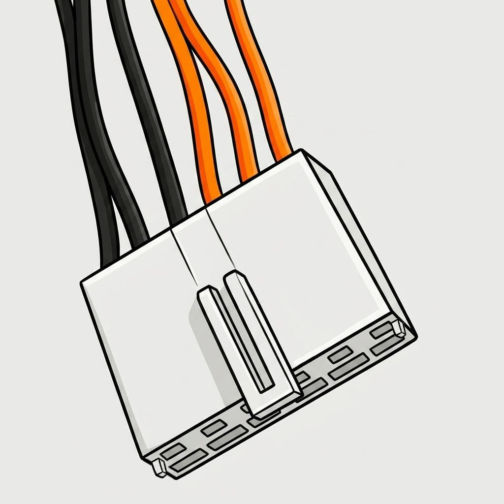
An additional connector on some AT PSUs, supplying power to certain legacy peripherals or drive controllers. Less common than the P8/P9 pair.
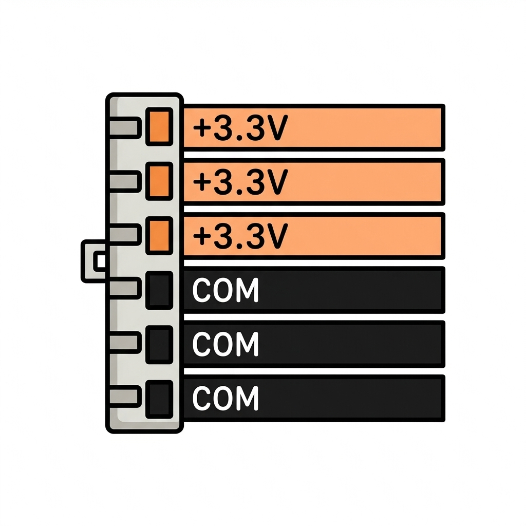
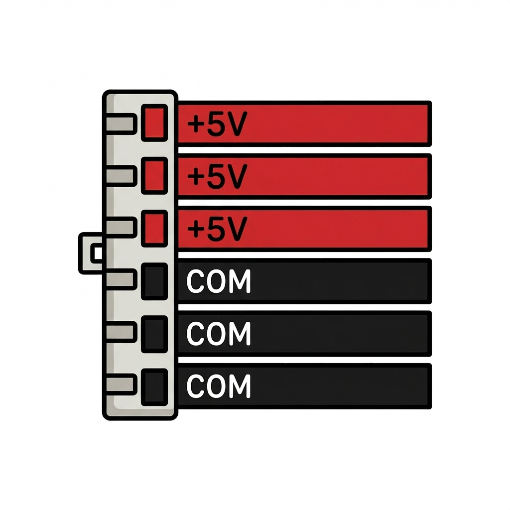
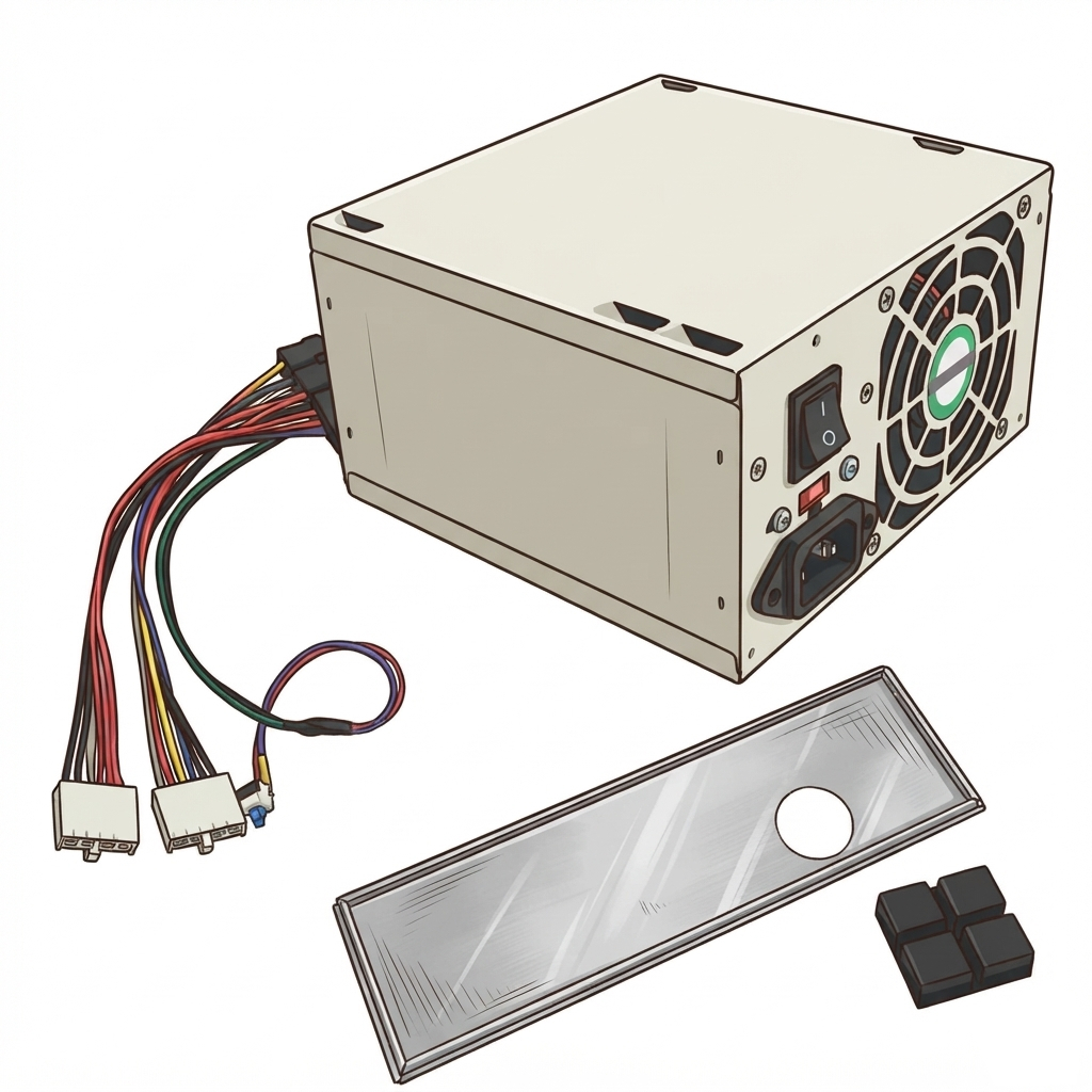
We also stock the accessories for an AT-era rebuild: self-locking AT power switches (standard and compact), AT I/O shields, and UK power cords. See our PSU Measurements guide for dimensions, or contact us for help identifying what your board needs.
Proprietary & Custom Connectors
Some NAS and server makers use proprietary power connectors rather than standard ATX — so a generic replacement PSU won't fit even if wattage and form factor match. These parts rarely show up on general electronics sites, and official replacements are often expensive or discontinued. Identifying and supplying these hard-to-find connectors is a specialism of ours — below are examples we currently support.
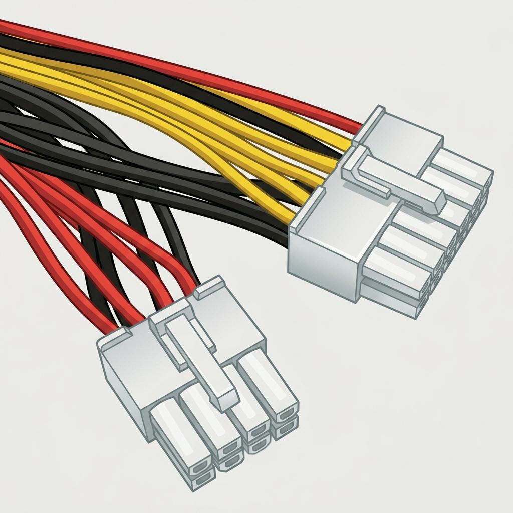
- Pins
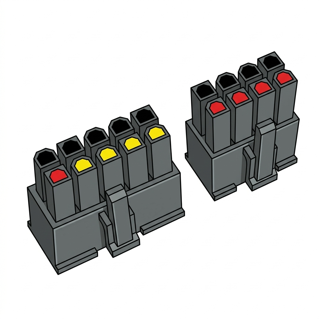
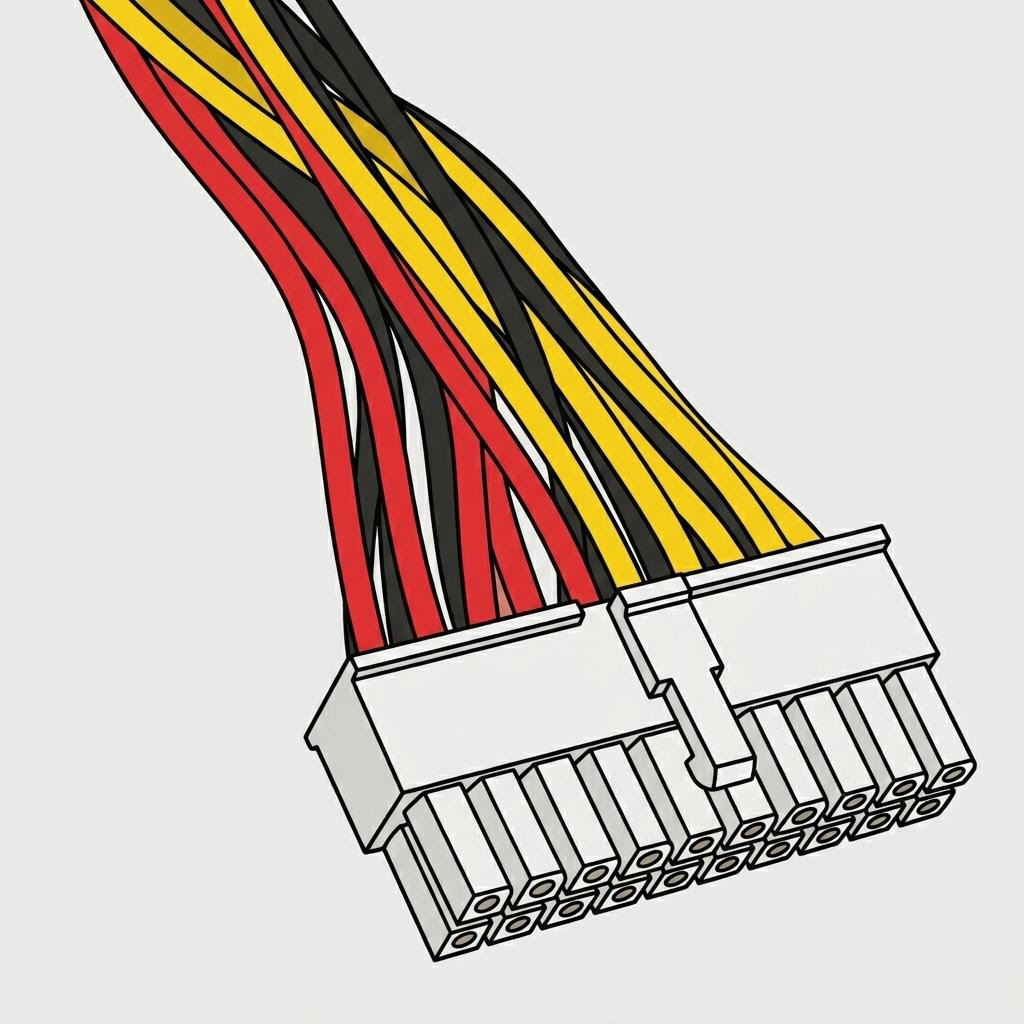
- 12 + 8 (dual connector)
- Used on
- Select Synology NAS units
- Status
- Proprietary — non-standard
A proprietary dual-connector layout on certain Synology NAS supplies, not found on standard desktop PSUs. We supply matching adaptor cables for compatible replacements.
- Pins
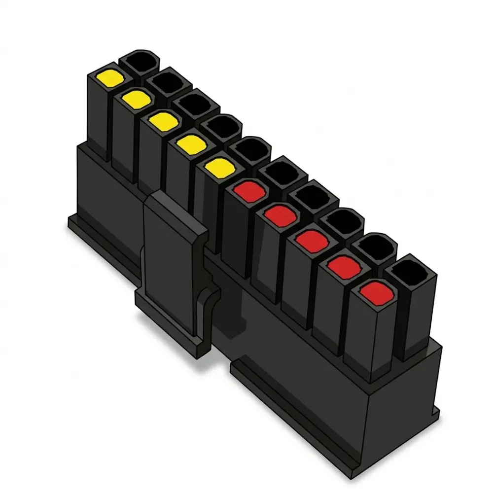
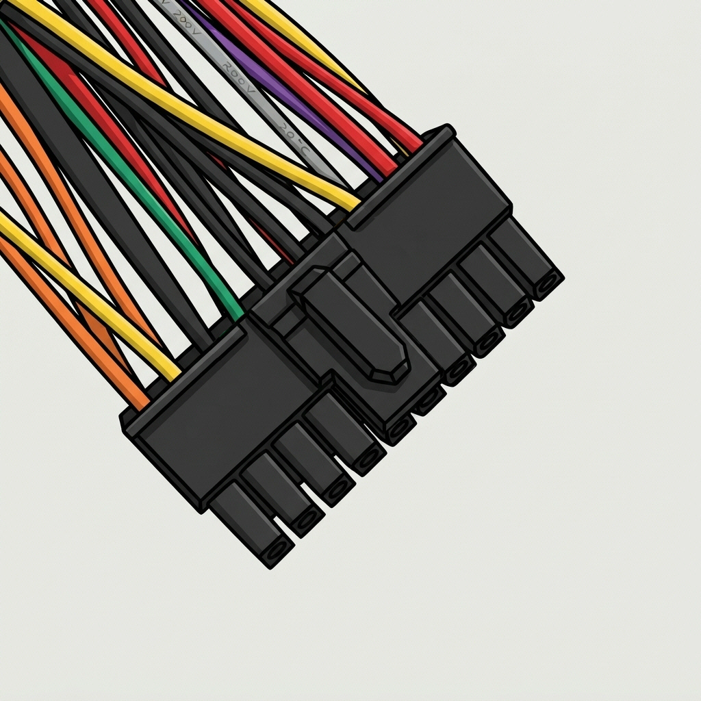
- 20
- Used on
- Select QNAP NAS units
- Status
- Proprietary — non-standard
QNAP's own 20-pin layout, distinct from a standard ATX 20-pin connector despite the matching pin count. We supply the correct adaptor cable for compatible replacements.
- Pins
- 20
- Used on
- Select Netgear ReadyNAS units
- Status
- Proprietary — non-standard
Netgear's own 20-pin layout on certain ReadyNAS models — pin count alone doesn't guarantee compatibility with a standard connector. We supply the correct adaptor cable for compatible replacements.
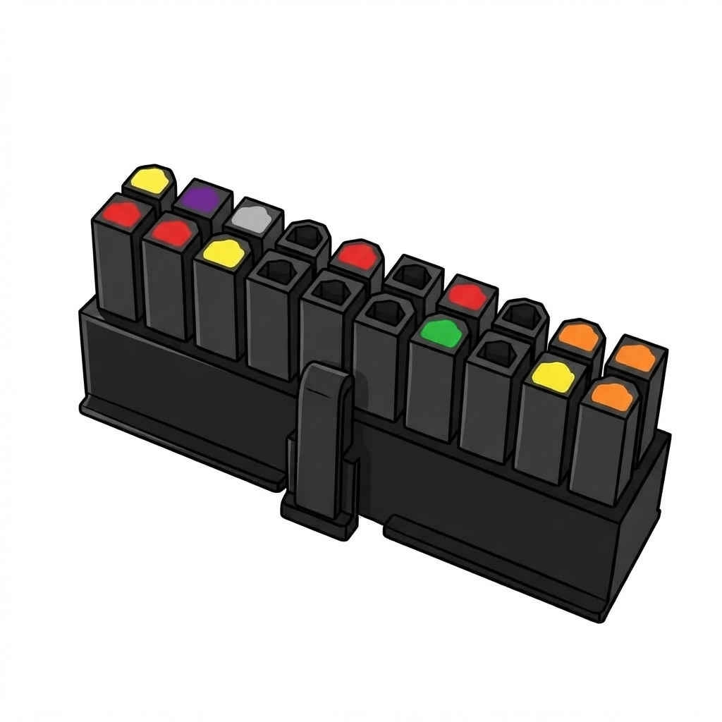
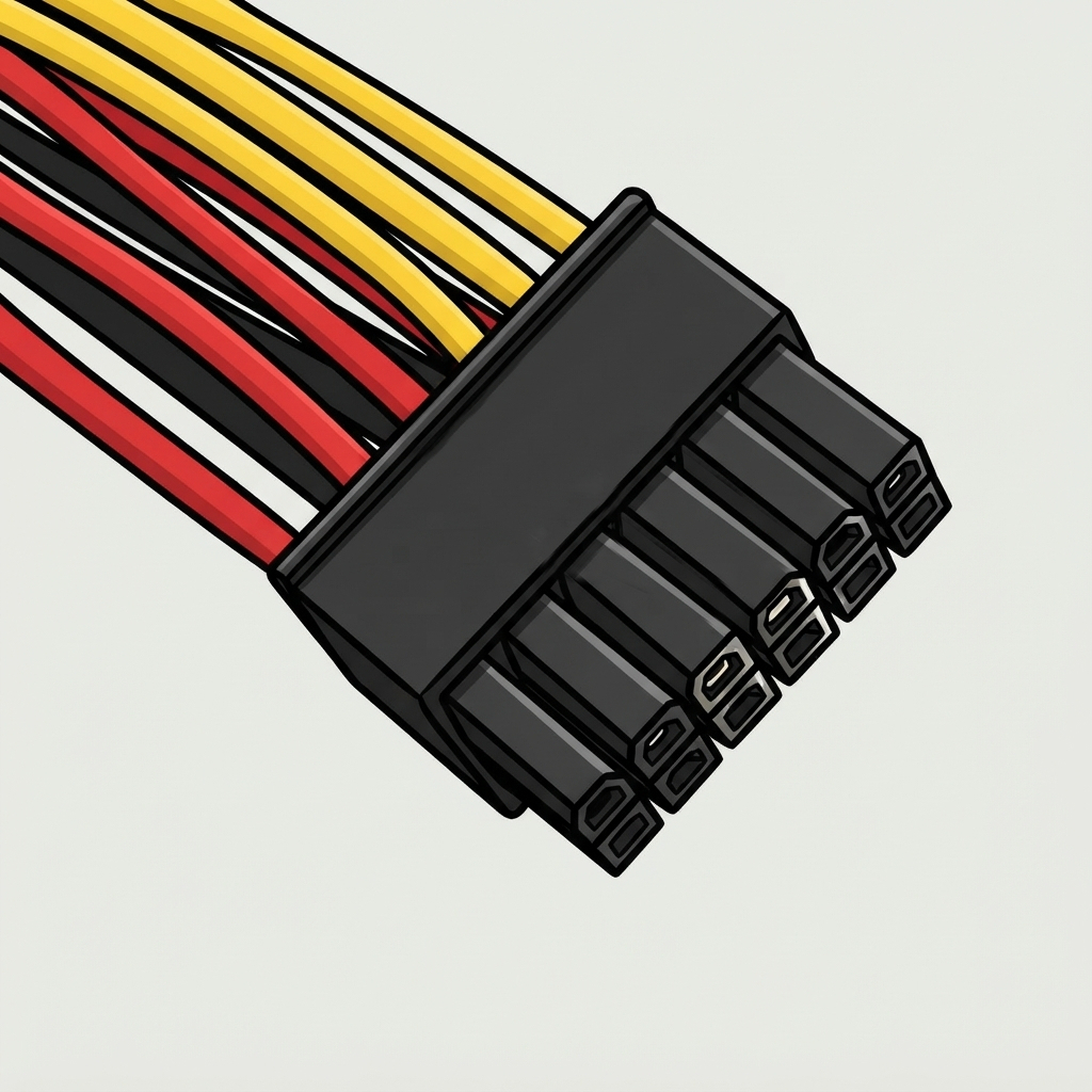
- Pins
- 12
- Used on
- Select Promise Pegasus RAID units
- Status
- Proprietary — non-standard
A proprietary 12-pin layout on certain Promise Pegasus RAID enclosures. Official replacements can be expensive and slow to source — we supply matching adaptor cables instead.
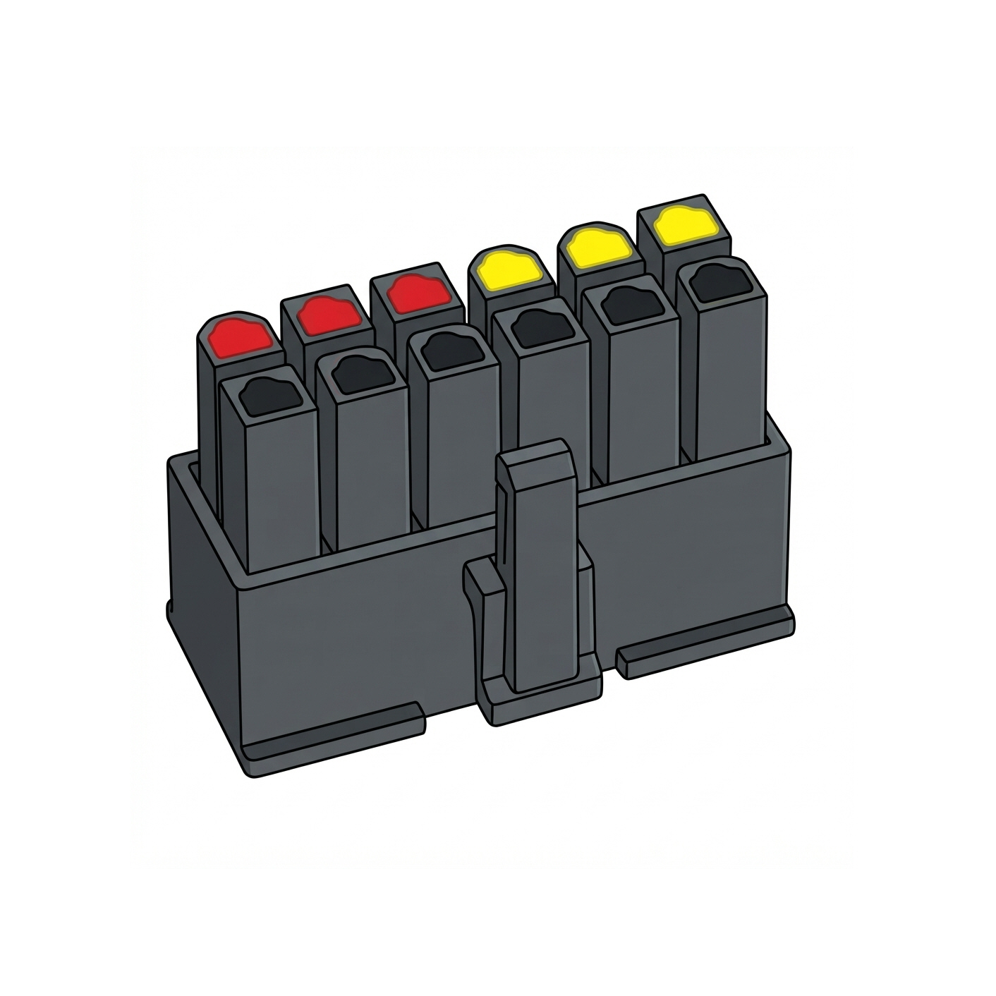
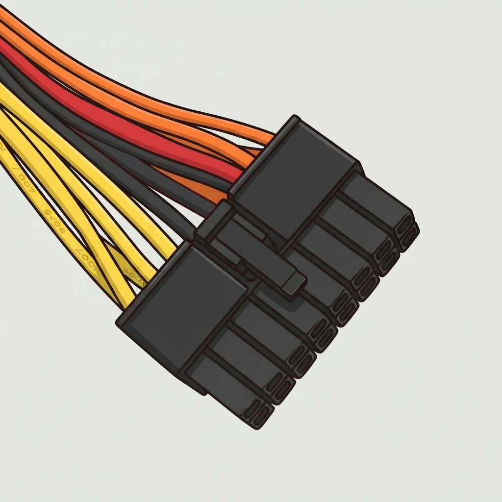
- Pins
- 16
- Used on
- Select Asustor NAS units
- Status
- Proprietary — non-standard
Asustor's own 16-pin layout on certain NAS models. Not something you'll find on a generic electronics site — we identify and supply the correct adaptor cable.
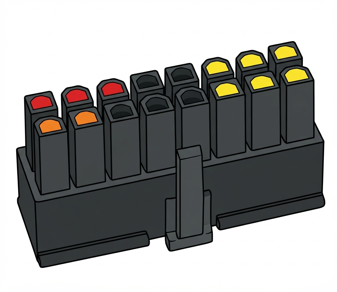
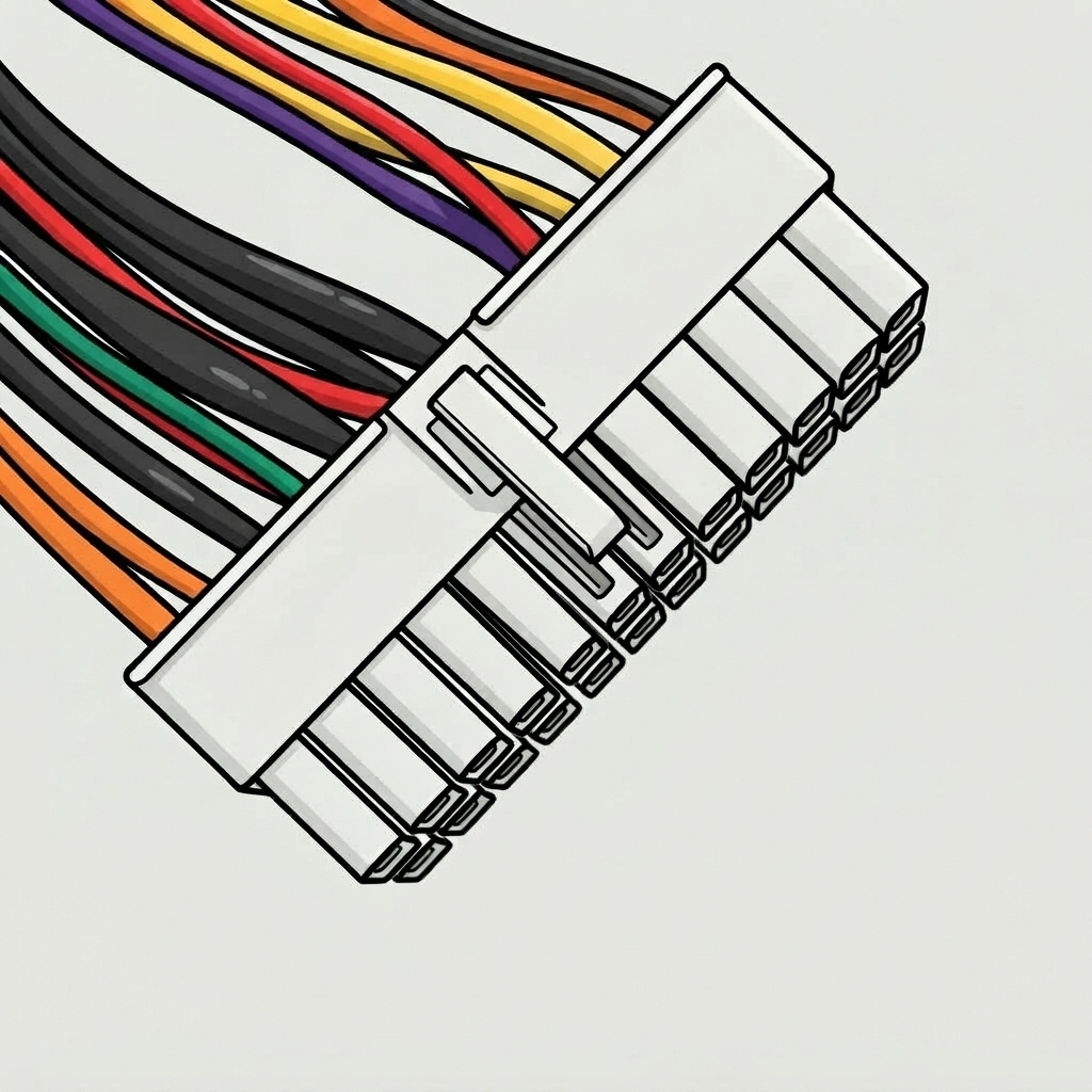
- Pins
- 24
- Used on
- Select Promise SmartStor NS4300N & NS4600N NAS units
- Status
- Proprietary — non-standard
Promise's own 24-pin layout on certain SmartStor NAS models, distinct from standard ATX despite the matching pin count — not compatible with standard ATX systems. We supply a direct replacement PSU — see our Cables & Adaptors range or contact us.
Quick Reference Table
Every connector, side by side.
| Connector | Pins | Voltage(s) | Status | Powers |
|---|---|---|---|---|
| ATX Main | 20/24 | 3.3V / 5V / 12V | Common | Motherboard |
| EPS CPU (4+4) | 8 | 12V | Common | CPU |
| EPS CPU (4-pin) | 4 | 12V | Occasional | CPU (older boards) |
| PCIe 6-pin | 6 | 12V | Occasional | Entry/mid GPU |
| PCIe 8-pin (6+2) | 8 | 12V | Common | Mid/high-end GPU |
| 12VHPWR / 12V-2x6 | 16 | 12V | Modern | High-end GPU |
| SATA Power | 15 | 3.3V / 5V / 12V | Common | HDD / SSD / optical |
| Mini SATA | 6 | 5V / 12V | Occasional | Compact drives |
| Molex 4-pin | 4 | 5V / 12V | Occasional | Fans, adaptors, older drives |
| Floppy (Berg) | 4 | 5V / 12V | Legacy | Fan controllers, adaptors |
| Auxiliary ATX | 6 | 3.3V / 5V | Legacy | Early-2000s boards |
| 3-Pin Fan | 3 | 12V | Legacy | Older PSU's own fan |
| P8 & P9 (AT) | 6+6 | 5V / 12V | Vintage | AT motherboards |
| P10 (AT) | 6 | 3.3V or 5V | Vintage | Legacy peripherals |
| Synology 12+8-pin | 20 | Proprietary | Proprietary | Select Synology NAS |
| QNAP 20-pin | 20 | Proprietary | Proprietary | Select QNAP NAS |
| ReadyNAS 20-pin | 20 | Proprietary | Proprietary | Select Netgear ReadyNAS |
| Promise Pegasus 12-pin | 12 | Proprietary | Proprietary | Select Promise Pegasus RAID |
| Promise SmartStor 24-pin | 24 | Proprietary | Proprietary | Select Promise SmartStor NS4300N/NS4600N NAS |
| Asustor 16-pin | 16 | Proprietary | Proprietary | Select Asustor NAS |
Not Listed Here?
|
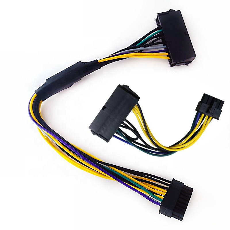
Synology, QNAP, Netgear, Promise and Asustor aren't the only makers using custom connectors — proprietary layouts turn up across NAS, RAID and server hardware. If your device uses a connector you don't recognise, send us a photo and we'll identify it and confirm if we can supply a matching cable. |
Quick-Reference Checklist
- Every ATX build needs both a 20/24-pin main connector and an EPS CPU connector — no substitute for either.
- Never force an 8-pin EPS connector into a PCIe GPU socket, or vice versa — they look alike but are wired differently.
- Yellow = +12V, red = +5V, orange = +3.3V, black = ground — this colour code holds across almost every modern PSU connector.
- Check your GPU's power requirement rather than assuming — high-end cards can need two or three 8-pin connectors, or one 12VHPWR/12V-2x6.
- A SATA cable without an orange wire isn't faulty — that +3.3V rail is rarely used by modern drives.
- P8/P9 AT connectors must be fitted with black ground wires together in the middle — match by pin position, not colour.
- P10 (AT) is usually +3.3V but occasionally +5V — confirm which your board needs.
- NAS and RAID units from Synology, QNAP, Netgear, Promise and Asustor sometimes use proprietary connectors — check before assuming a standard PSU fits.
- Missing a connector? An adaptor likely exists — see our Cables & Adaptors range before assuming you need a new PSU.
- Still unsure? Contact us with your PC, NAS or GPU model and we'll confirm the right connector.